Gas Supply

|
To avoid equipment damage, do not extend gas flue exhaust stack. |
This may impair proper operation of the burner, causing malfunctions and possible negative back draft.
The gas open fryer is factory available for either natural or propane gas. Check the data plate inside the left front door of the cabinet to determine the proper gas supply requirements. The minimum supply for natural gas is 7 inches water column (1.7 kPa) (17.0 mbar), and 10 inches water column (2.49 kPa) (24.9 mbar) for propane.
|
|
To avoid personal injury and/or property damage, use only type of gas specified on data plate. |
|
|
Explosion Risk To avoid possible serious personal injury:
|
Provisions should be made for moving the open fryer for cleaning and servicing. This may be accomplished by:
-
Installing a manual gas shutoff valve and a disconnect or union.
-
Installing a heavy-duty design CSA certified connector. In order to be able to service this appliance, which is provided with casters, a connector complying with ANSI Z21.69-CAN 6.16 or CAN 1-6.10m88 and a quick-disconnect device, complying with ANSI Z21.41or CAN 1-6.9m70, must be installed. It must also be installed with restraining means to guard against transmission of strain to the connector as specified in the appliance manufacturer’s instructions.
-
See the illustration on the following page for the proper connection of flexible gas line and cable restraint.
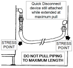
NOTE: The cable restraint limits the distance the open fryer can be pulled from the wall. For cleaning and servicing the unit, the cable must be unsnapped from the open fryer and the flexible gas line disconnected. This allows better access to all sides of the open fryer. The gas line and cable restraint must be reconnected once the cleaning or servicing is complete.
Gas Piping
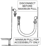
Distance from Wall
|
Correct |
Wrong |
|
|
|
Minimum pull of equipment from wall permissible for accessibility to quick disconnect device. |
Avoid sharp bends and kinks when pulling equipment away from wall. Maximum pull will kink ends, even if installed properly, and reduce connector life. |
Cable Restraint
For Australia or New Zealand Only: Where a model is supplied with castors and is to be connected to a fixed gas supply via a flexible hose connection, a restraining chain or wire of adequate strength shall be fixed to the appliance and be suitable to be fixed to the wall within 50 mm of each connection point. The length of the chain or wire shall not exceed 80% of the length of the hose assembly.
Secure I-bolt to building using acceptable building construction practices.
Permanently connected electric fryers with casters must be installed with flexible conduit and a cable restraint, when installed in the United States and internationally. Holes are available in the rear fryer frame for securing the cable restraint to the fryer. The cable restraint does not prevent the fryer from tipping.
Ensure the cable restraint on moveable gas fryers is installed as shown.
The flexible gas hose cannot exceed 2M in length.

|
DRYWALL CONSTRUCTION |
Secure unit to building stud approximately six inches either side of service connection. Use cable restraint that is at least six inches short than flexible conduit. |
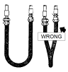
Couplings Installation
|
Correct |
Wrong |

|
|
|
Couplings and hose should be installed in the same plane. |
To avoid torsional twisting and undue strain leading to product failure, do not offset couplings. |
Metal Hose Installation
|
Correct |
Wrong |

|

|
|
Install the metal hose for vertical traverse as shown. Note the single, natural loop. |
To avoid straining and twisting the metal hose to a point of early failure at the coupling, do not allow a sharp bend, as shown. |
Bending at Coupling
|
Correct |
Wrong |

|

|
|
Maintain the minimum or larger bending diameter between the couplings. |
To avoid creating double bends leading to failure of fittings, do not lessen diameter at the couplings, as shown. |
Horizontal Self-Draining Installation
If self-draining is not necessary, connect metal hose in a vertical loop.
|
Correct |
Wrong |

|

|
|
If self-draining is necessary, use support on lower plane as shown. |
Do not connect metal hose horizontally without support as shown. |
Gas Leak Test
NOTE: Prior to turning the gas supply on, be sure the gas valve knob on the gas control valve is in the off position.
Upon initial installation, and after moving the unit, the piping and fittings should be checked for gas leaks. A simple checking method is to turn on the gas and brush all connections with a soap solution. If bubbles occur, it indicates escaping gas. In this event, the piping connection must be redone.
|
|
Fire or Explosion Risk To avoid personal injury and/or property damage, do not use lighted match or open flame to text for gas leaks. |
Gas Pressure Regulator Setting
|
NOTICE - |
Gas pressure regulator has been set by manufacturer and should not be adjusted by user. |
The gas pressure regulator on the gas control valve is factory set as follows:
-
Natural: 3.5 inches water column (0.87 kPa) (8.72 mbar).
-
Propane 10.0 inches water column (2.49 kPa) (24.9 mbar).
Measuring Gas Pressure
|
NOTICE - |
Gas pressure regulator has been set by manufacturer and should not be adjusted by user. |
|
|
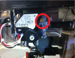
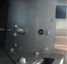
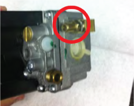
-
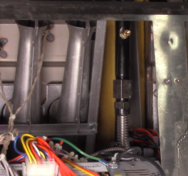
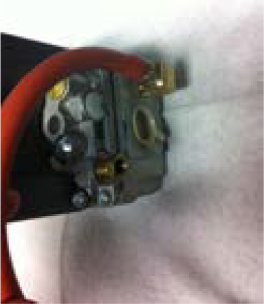
Locate the pressure tap hole or fitting on the side of the gas valve. If necessary, remove the pipe plug from the valve or fitting as shown.
-
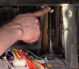
If necessary, screw a pressure tap fitting into the valve or the fitting on the side of the valve.
-
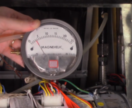
Place one end of a vacuum hose on the pressure tap fitting and the other end on the manometer.
-
Turn the fryer “ON”.
-
Allow the fryer to reach full burn.
-
The pressure reading on the manometer should be 3.5” of water column for Natural gas and 10” of water column for LP gas.
-
Turn the fryer off.
-
Remove the pressure tap fitting.
-
Place the pipe plug back into the valve or the fitting on the valve.