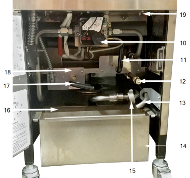
Operating Components
|
|
| Item No. | Description | Function | ||
|---|---|---|---|---|
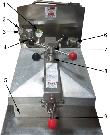
| 1 | Pressure Gauge | Indicates the pressure inside the vat. | ||
| 2 | Safety Relief Valve Ring |
|
||
| 3 | Safety Relief Valve |
This is an ASME approved spring loaded valve, set at 14.5 psi; if the deadweight assembly is clogged, this safety valve releases excess pressure, keeping the vat chamber at 14.5 psi (999 mbar).
|
||
| 4 | Deadweight Assembly |
This deadweight style, pressure relief valve maintains a constant level of steam pressure within the vat; excess steam is vented through the exhaust stack.
|
||
| 5 | Vat | Holds the cooking oil and an adequate cold zone for collection of cracklings. | ||
|
6 |
Solenoid Valve |
An electromechanical device that causes pressure to be held in the vat; the solenoid valve closes at the beginning of the Cook Cycle and is opened automatically by the controls at the end of the cook cycle; if this valve becomes dirty or the Teflon seat nicked, pressure won’t build and must be repaired. |
||
| 7 | Spindle Assembly | An assembly that is tightened after the lid is latched, and applies pressure to the top of the lid; the lid gasket applies pressure against the vat rim; after building one pound of internal pressure, the lid liner pushes a locking pin into the locking collar, preventing the spindle from being turned while the vat is pressurized. | ||
| 8 | Lid Limit Stop | A threaded adjustable collar used to obtain the proper tightness between the lid gasket and the vat rim; done by controlling the number of clockwise rotations of the spindle. | ||
| 9 | Lid Latch | A spring loaded latch that provides a positive latch to hold the lid closed; this latch, along with the spindle assembly and lid gasket, provides a pressure sealed vat chamber. | ||
| 10 | Gas Control Valve (Gas Models Only) | Controls the gas flow to the burner. | ||
|
11 |
Filter Valve |
When the power switch is in the pump position, this two-way valve directs filtered oil from the filter pan, back into the vat. |
||
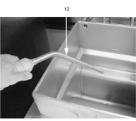
| 12 | Rinse Hose (Optional) | A hand-held hose used to rinse food particles from the vat into the filter pan; attaches to a quick disconnect fitting. | ||
| 13 | Condensation Drain Line | A hose used to route the condensation collected within the steam exhaust system, to the condensation pan. | ||
| 14 | Condensation Drain Pan | The collection point for the condensation, formed within the steam exhaust system; remove and empty periodically. | ||
| 15 | Filter Union | Connects the filter to the filter pump, and allows easy removal of the filter pan. | ||
|
16 |
Filter Pan |
The removable pan that houses the filter and catches the oil when it is drained form the vat; it is also used to remove and discard old oil.
|
||
| 17 | Drain Valve (Only the Handle is Shown) | A two-way ball valve that is normally closed; turn the handle to drain the oil from the vat, into the filter pan. | ||
| 18 | Drain Interlock Switch | A microswitch that provides protection for the vat in the
event an operator inadvertently drains the oil from
the vat while the main power switch is on; the switch automatically
shuts off the heat when the drain valve is opened.
|
||
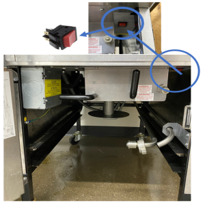
| 19 | High Temperature Limit |
A control that senses the temperature of the oil; if the temperature of the oil exceeds the safe operating limit, this control opens and shuts off the heat to the fryer; when the temperature of the oil drops to a safe operation limit, the control must be manually reset by pressing the red rocker switch for 5 seconds. It's located under the control panel, behind the door.
|
||
| 19
|
High Temperature
Limit
|
A control that senses the temperature of the oil; if the temperature of the oil exceeds the safe operating limit, this control opens and shuts off the heat to the fryer; when the temperature of the oil drops to a safe operation limit, the control must be manually reset by pressing the red reset button, located under the control panel, behind the door. |
||
|
||||
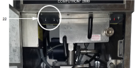
| 20 | Transformer | Reduces the voltage down to accommodate those components with low voltage. | ||
|
21 |
Circuit Breaker (Single Phase Electric Models Only) |
Opens the electrical circuit, and removes power to elements. |
||
| 22 | Circuit Breakers (Electric Models Only) | A protective device which breaks the circuit when the current exceeds the rated value. | ||
| 23 | Contactors (Electric Models Only) | Relays the route power to the heating elements; one relay is in series with the high limit, the other one is in series with the controls. | ||
| 24* | Lid Spring | Assists in raising the lid, then holding it open (shield covered). | ||
| 25* | Condensation Drain Channel | This channels the moisture, that collects on the inner liner when the lid is opened, into the drain line and prevents the moisture droplets from falling into the oil. | ||
|
26* |
Lid Gasket |
Provides the pressure seal for the vat chamber. |
||
| 27* | USB Port |
C8000 ARM control’s USB port is located inside an access cover on the back of the control. Remove the control panel screws and lower the control panel to the service position. When inserting a flash drive, the label or logo should face away from you. (missing or bad snippet) |