|
POWER/PUMP Switch |
A three way switch with center OFF position; move the switch to the position marked POWER to operate the fryer; move the switch to the position marked PUMP to operate the filter pump; certain conditions must be met prior to operation of the filter pump; these conditions are covered later in this section. |
|
Vat |
This reservoir holds the cooking oil, and is designed to accommodate the heat exchanger, 8 head of product and an adequate cold zone for collection of cracklings |
|
Carrier |
This stainless steel carrier consists of five racks which contain the food product during and after frying |
|
Drain Valve |
A two-way ball valve, normally in the closed position; turn the handle to drain the oil from the vat into the filter pan |
|
Drain Interlock Switch |
A microswitch that provides protection for the vat in the event an operator inadvertently drains the oil from the vat while the main switch is in the POWER position; the switch is designed to automatically shut off the heat when the drain valve is opened |
|
Oil Mixing System |
A oil mixing capability to help ensure oil is properly mixed to prevent an accumulation of moisture and hence boiling action in the vat; the filter pump is activated by the controls, at preset intervals, to mix the oil |
|
Air Valve |
Pumps air into the oil, periodically, to keep the oil at a uniform temperature; this only functions when the unit has been sitting idle for a period of time, and when heating up from a cold start. |
|
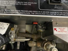
High Limit
|
This high temperature control senses the temperature of oil; if the temperature of the oil exceeds 450°F (230°C), this control will open and shut off the heat to the vat; when the temperature of the oil drops to a safe operation limit, the control must be manually reset by pressing the red reset button, located under the control panel, in the right, front of the fryer. A control that senses the temperature of the oil; if the temperature of the oil exceeds the safe operating limit, this control opens and shuts off the heat to the fryer; when the temperature of the oil drops to a safe operation limit, the control must be manually reset by pressing the red rocker switch for 5 seconds. The red rocker switch is located under the control panel.
|
|---|---|
|
Filter Pan |
The removable pan that houses the filter and catches the oil when it is drained from the vat; also used to remove and discard old oil. |
|
Filter Union |
Connects the filter to the filter pump, and allows easy removal of the filter and filter pan |
|
Fuses |
A protective device which breaks the circuit when the current exceeds the rated value |
|
USB Port |
C8000 ARM control’s USB port is located inside an access cover on the back of the control. Remove the control panel screws and lower the control panel to the service position. When inserting a flash drive, the label or logo should face away from you. |

|
Shock Hazard Access covers for fryers with Pressure Assist are connected with electrical wiring to the control. To avoid electrical shock, a service technician must perform any activities related to the USB port. |