|
|
|
Installing
Due to the variations of equipment installations from one store to another, we are providing only a general process which the installer can use for reference or as a checklist. All electrical, water, and drain connections must comply with all federal, state, county, and local codes.

|
Shock Hazard To avoid property damage, do not puncture unit with tools during unpacking. |
|
NOTICE - |
ALL units MUST have a water supply connection and a plumbed drain. |
|
NOTICE - |
When locating, moving, or positioning the holding cabinet, be careful not to scratch the table surface. |
AHC-990
- Position cabinet so controls are accessible.
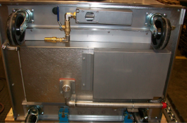
-
Locate the cold water fill line and drain is under the unit.
-
Layout routing of 1/4 inch fill line from the holding cabinet male quick disconnect under the unit to a cold water source. (Both male & female disconnects are supplied with the units)
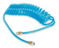
-
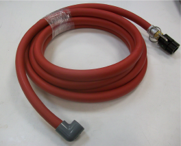
Using an 1/8” to 1/4” reducer, a 1/4” x 6 ft. coiled hose (see below) can be attached to the female disconnect and the coiled hose is then connected to the in-coming water line.
-
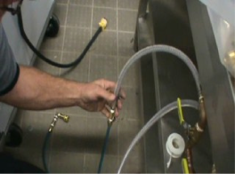
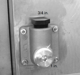
Layout routing of drain line from a 3/4” side outlet or 1” bottom outlet in drain block under unit to an open drain.
-
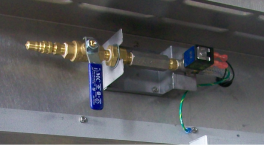
Several options are available for the AHC-990 drains:
-
Install cabinet over floor drain for nightly draining.
-
Disconnect water line and roll cabinet to nearest floor drain for nightly draining.
-
Use the Henny Penny drain kit, part no. 03697 for nightly draining. See photo at left.
-
-
Connect water line to holding cabinet.
-
Connect electrical power to unit.
-
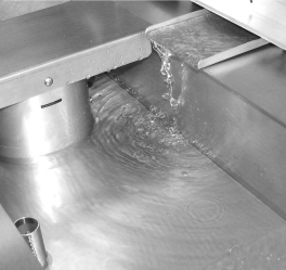
Be sure fill tray angles down so water flows freely into pan.
-
Check cabinet for proper operation and repair any water leaks.
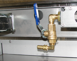
|
NOTICE - |
If necessary, the shut-off valve under the unit can be used to help regulate the water flow into the water pan. Normally, these should be opened fully. |
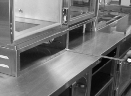
AHC-993
-
Position cabinet so controls face the store’s drive-thru area.
-
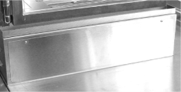
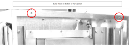
Remove 2 screws and bottom panel at front of unit.
-
Remove 2 screws and bottom panel at rear of unit.
-
Measure and center unit front to rear on the table top with one side flush with the table end.

-
Using the holes in the cabinet base as guides, mark 4 mounting hole locations in the table top.
-
Layout routing of 1/4 inch fill line from the holding cabinet male quick disconnect under the unit to a cold water source.
-
Layout routing of drain line from a 3/4” side outlet or 1” bottom outlet in drain block under unit to an open drain.
-
Layout routing of electrical power cord from the top of the cabinet to the proper receptacle.
-
Measure, mark, and drill or cut holes or other openings in table top and/or shelves as dictated by this specific installation to permit routing of water, drain, and electrical lines.
-
Fabricate the planned drain line.
-
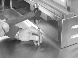
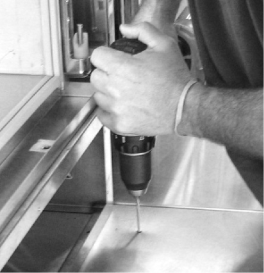
Move unit to expose two marks at the front, center punch each mark, and drill 3/16” pilot holes.
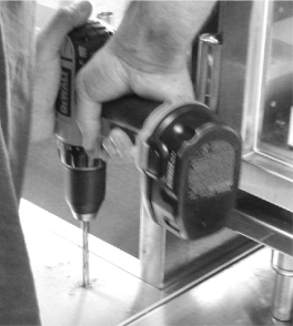
-
Drill final holes using a 5/16” bit. Clean up all debris and metal shavings.
-
Position unit so the holes in the table top align with the mounting holes in the base.
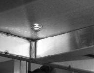
-
Install four 1/4” stainless steel screws and flat washers from underneath table and install four stainless steel flat washers and lock nuts on screws from above the base lip.
-
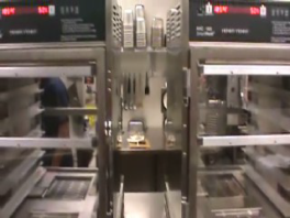
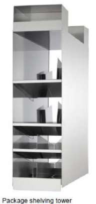
993’s should have about 10” of clearance between them to accommodate the packaging shelving tower (see below).
-
Perform a final positioning of the cabinet with one side flush with the table end and centered front to back on the table top.
- Tighten the fours bolts and nuts securely.
-
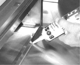
Apply a bead of clear silicone sealer around cabinet base to fill gaps between table top and base.
-
Connect water line and drain line to holding cabinet.
-
Connect electrical power to unit.
-
Enure fill tray angles down so water flows freely into pan.
-
Check cabinet for proper operation and repair any water leaks.
-
Install bottom panel at front of unit with 2 screws.
- Install bottom panel at rear of unit with 2 screws.
|
NOTICE - |
If necessary, the shut-off valve under the unit can be used to help regulate the water flow into the water pan. Normally, these should be opened fully. |