Error Codes
In the event of a control system failure, the digital an error message displays. The message codes are shown in the DISPLAY column below. A constant tone is heard when an error code displays, and to silence this tone, press any button.
| 
                                                                     Display  | 
                                                                
                                                                     Cause  | 
                                                                
                                                                     Correction  | 
                                                            
|---|---|---|
| 
                                                                     “E-4”  | 
                                                                
                                                                     Control board overheating.  | 
                                                                
                                                                     Turn switch to OFF position, then turn switch back to ON; if “E-4” displays, the control board is getting too hot; check the louvers on each side of the unit for obstruction.  | 
                                                            
| 
                                                                     “E-5”  | 
                                                                
                                                                     Oil overheating.  | 
                                                                
                                                                     Turn switch to OFF position, then back to ON; if “E-5” displays, the heating circuits and temperature probe should be checked.  | 
                                                            
| 
                                                                     “E-6A”  | 
                                                                
                                                                     Temperature probe open.  | 
                                                                
                                                                     Turn switch to OFF position, then back to ON; if “E-6” displays, the temperature probe should be checked. 
  | 
                                                            
| 
                                                                     “E-6B”  | 
                                                                
                                                                     Temperature probe shorted.  | 
                                                            |
| 
                                                                     “E-10” "E-10 A" "E-10 B" "E-10 C" "E-10 D" "E-10 F" "E-10 M" "E-10 Y"  | 
                                                                
                                                                     High limit High limit tripped above 300° F High limit tripped below 300° F High limit tripped while cooking High limit tripped less than 5 minutes of Auto Filter High limit tripped during filter cycle High limit tripped during melt mode High limit tripped less than 5 minutes of "YES"  | 
                                                                
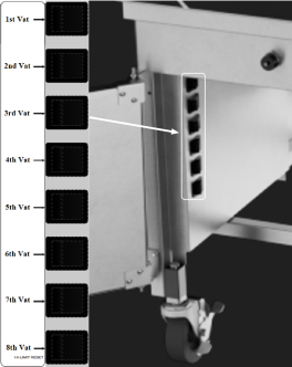
                                                                     Let the unit cool down (15-20 minutes), reset the high limit by pressing and holding the appropriate high limit reset switch for 5 seconds. If high limit does not reset, contact service provider. (Vat 1 refers to the far-left vat.) For single well units, open door and the reset switch is located up and underneath. 
                                                                          | 
                                                            
| 
                                                                     “E-15”  | 
                                                                
                                                                     Drain switch.  | 
                                                                
                                                                     Ensure drain knob is completely pushed-in; if E-15 per- sists, have drain switch checked.  | 
                                                            
| 
                                                                     “E-18A”  | 
                                                                
                                                                     Left level sensor open.  | 
                                                                
                                                                     Turn switch to OFF position, then back to ON; if display still indicates a failed sensor, have the connections checked on the control board. Have sensor check and replaced if necessary. 
 
  | 
                                                            
| 
                                                                     “E-18B”  | 
                                                                
                                                                     Right level sensor open.  | 
                                                            |
| 
                                                                     “E-18C”  | 
                                                                
                                                                     Both level sensors open.  | 
                                                            |
| 
                                                                     “E-21”  | 
                                                                
                                                                     Slow heat recovery.  | 
                                                                
                                                                     Have a certified service technician check the fryer for cor- rect voltage to the unit; have heat circuit checked; have unit checked for loose or burnt wires.  | 
                                                            
| 
                                                                     “E-22” ”NO HEAT” ”CHECK PWR CORD AND BREAKER”  | 
                                                                
                                                                     Elements not heating.  | 
                                                                Have power cord and heat circuit checked. | 
| "E-31" | Elements are up | Lower elements completely into vat. | 
| 
                                                                     “E-41” ”E-46”  | 
                                                                
                                                                     Programming failure.  | 
                                                                
                                                                     Turn power switch to OFF, then back to ON; if an error code displays, have the controls re-initialized; if error code persists, have the control board replaced.  | 
                                                            
| 
                                                                     “E-47”  | 
                                                                
                                                                     Analog converter chip or 12-volt supply failure.  | 
                                                                
                                                                     Turn power switch OFF, then back to ON; if “E-47” per- sists, have the I/O board, or the PC board replaced; if speaker tones are quiet, probably I/O board failure; have the I/O board replaced.  | 
                                                            
| 
                                                                     “E-48”  | 
                                                                
                                                                     Input system error.  | 
                                                                
                                                                     Have PC board replaced.  | 
                                                            
| 
                                                                     “E-54C”  | 
                                                                
                                                                     Temperature input error.  | 
                                                                
                                                                     Turn power switch to OFF, then back to ON; have control PC board replaced if “E-54C” persists.  | 
                                                            
| 
                                                                     “E-60” “FILTER IN USE”  | 
                                                                
                                                                     AIF PC board not communicating with PC board.  | 
                                                                
                                                                     Turn power switch to OFF, wait 15 seconds, then turn switch back to ON. If “E-60 persists, have connector be- tween the PC boards checked; replace AIF PC board or control PC board if necessary.  | 
                                                            
| 
                                                                     “E-70C”  | 
                                                                
                                                                     Drain valve jumper wire missing or disconnected.  | 
                                                                
                                                                     Have the jumper wire checked on the PC board at drain switch interlock position.  | 
                                                            
| 
                                                                     “E-93” ”24 VDC SUPPLY TRIPPED”  | 
                                                                
                                                                     Autolift motor malfunction or failure.  | 
                                                                
                                                                     If AutoLift feature is not operating, have each of the Auto- lift motors checked. Check the 24V circuits.  |